LINK’s Global Team of Experts Come Together for Largescale Customer Installation

Jul 7, 2023

As a collaborative effort between Tescor and Link Engineering Company, the Link Group, Inc. companies successfully installed a large drive-in chamber for new electric vehicle environmental simulation testing for a California-based customer. The cross-functional LINK team supported this installation using their highly experienced staff across four business units, ranging from multiple locations in Michigan to Pennsylvania. This largescale support allowed for quick and efficient installation as well as a vast knowledge base provided by the LINK team.

An automotive OEM and LINK customer was in need of a walk-in-style environmental chamber for the testing of a newly-developed electric vehicle. As an engineered-to-order thermal solutions provider, Tescor, a Link Group Company, was called upon to deliver a custom-built chamber that matched the customer’s unique specifications. The chamber was required to encase the full vehicle while simulating rigorous environmental conditions.

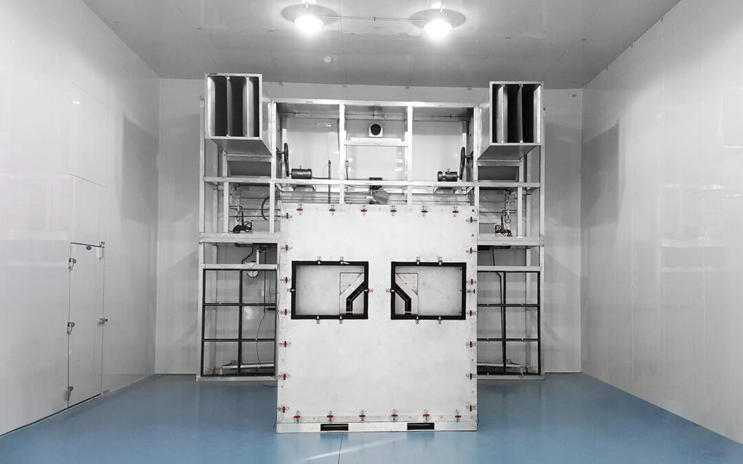
The chamber is designed so that the vehicle can drive directly into the chamber and park facing the evaporator as the tests are conducted. Thus, the exterior dimensions of the chamber are nearly 51 feet long by 21 feet wide and 15 feet tall. Tescor’s innovative solution includes the ability for the customer to attach a vehicle to hubcap dynamometers and run at simulated speeds up to 177mph. The chamber provides an environment with temperatures between -40°C and 60°C with humidity ranges between 20% and 65%. The vehicle is ran at steady state conditions at the extremes of the above ranges. Using Tescor’s chamber, the customer also has the ability to test the vehicle in a ramping temperature situation of 20°C to -20°C over 100 minutes.

The chamber itself was constructed one panel at a time using strategic interlocking panel technology. The build started from the front of the chamber at the doors: first the flooring was laid, followed by part of a wall, and finally, the ceiling. The ceiling was continuously supported as the team moved to the back of the unit onto the next section. Using a forklift, the LINK team was required to lift sizeable beams to the top of the chamber to secure the ceiling in place one section at a time. Since this chamber will reside in California, an additional cage was needed around the structure to support it in the event of an earthquake. The evaporator also received its own external supportive structure.

Four beams were placed vertically, two on either side of the chamber, each supporting a single beam that runs across the width of the chamber. The evaporator was then threaded to these beams through the ceiling. The evaporator, which is approximately 15 feet long, 6 feet wide, and 5 feet high, was suspended using a frame constructed outside of the chamber at 22 feet long and 16 feet high. Every panel was numbered and predrilled at Tescor to run conduits, cooling lines, and more, exemplifying the level of detail and prework put into the product prior to its arrival at the customer’s facility.

Installing the chamber took approximately a week and a half to fully erect and assemble. The team consisted of staff members across four LINK facilities, including seven for the first week and six for the second week, with an electrician arriving from Tescor toward the end of the installation. Team members hailed from the Tescor facility in Westminster, PA, as well as several LINK sites across Plymouth, MI; Dearborn, MI; and Ottawa Lake, MI. The unique skill sets and expertise possessed by the LINK team created a complementary environment and allowed for a quick turn-around of a complex task.

The team diligently worked approximately 100 hours on the first week and 100 hours on the second week, with the chamber being fully operational on week three. The work was completed under close supervision from the customer’s safety team. Thanks to the collaboration of team members across LINK, the customer was provided with remarkable service and support, in addition to a customized environmental chamber for state-of-the-art automotive testing.

Link Group, Inc. (LINK), parent to Link Engineering Company, Link Industries, and Tescor, consists of businesses that offer customized solutions, with a focus on delivering high value to each of their customers. Offerings consist of the design and manufacture of customized, high precision test, research, simulation, quality control and thermal solution equipment; comprehensive test services; and high precision cutting tools. LINK’s corporate headquarters are in Plymouth, Michigan (US), with manufacturing and design facilities, laboratory and vehicle test operations, and support teams around the world.

Contact Us

LINK has been committed to cultivating positive growth and advancing the testing industry since our founding in 1935. Let us help you with a customized testing solution for your next project.

Contact Us

Check out our other blogs

You are now leaving Link Engineering

Link Engineering provides links to web sites of other organizations in order to provide visitors with certain information. A link does not constitute an endorsement of content, viewpoint, policies, products or services of that web site. Once you link to another web site not maintained by Link Engineering, you are subject to the terms and conditions of that web site, including but not limited to its privacy policy.

You will be redirected to

Click the link above to continue or CANCEL

Brakes

Type of TestTest HighlightsEquipment UsedExample Procedures
Chemical TestingMeasurement of copper, asbestos and other elements in brake friction materialsICP-OES / PLMJ2975
Materials TestingPhysical properties including quality control for friction, wear, compressive strain, shear strength, corrosion resistance, swell and growthChase Machine / Compressibility Machine/ Shear Machine / Corrosion Chamber / Environmental Chamber / OvenJ661, ISO 6310, ISO 6311, ISO 6312, ABNT NBR 9301, ABNT NBR 5505, ABNT NBR 5537, ASTM B117
Frequency ResponseComponent Frequency ResponseLaser Vibrometer Test StandSAE J2933, J3001, J2598, L-4375
Structural Fatigue and
Durability
Breaking strength, cyclic fatigueServo Hydraulics, Torque FlexJ2995, C419, C441, GMW18022
Caliper FingerprintingCaliper characteristics such as knockback, rollback, fluid displacement, deflection...Caliper Test Bench / Brake DynamometerL-4177, PF.90257
Brake Drag and DTVResidual drag, disc thickness variation, brake feel and vehicle fuel mileageOff Brake Drag Stand / Brake DynamometerJ2923, GMW14926, GMW14351, PF.90257, L-13080
PerformanceHydraulic, air and electric brakes, friction levels, stopping distance, corrosion, cleanability, brake torque variation, rotor cracking, regulation, stability control, coastdownBrake Dynamometer, Model 4000 DASJ2784, J2928 IS026867, GMW14985, PF.90210, PF.90244, L-405, FMVSS 121, FMVSS 122, FMVSS 105, FMVSS 135, FMVSS 126, FMVSS 136, ECE R13H, AMS
WearRotor wear, drum wear, lining wear, DTV, durability, city traffic, suburban trafficBrake Dynamometer, Model 4000 DASJ2707, USCT, L-423, PF.90244, Los Angeles, Detroit, Phoenix, Birmingham, Marquette
NVHBrake squeal during drag and decel events at different temperatures, pressure and torque levelsNVH Brake DynamometerJ2521, L420, 1430, GMW17427, PF. 90244
Brake EmissionsBrake dust particle size, count, concentration and massBrake DynamometerWLTP, CARB, Duty cycle

Hubs/Bearings

Type of TestTest HighlightsEquipment UsedExample Procedures
Wheel BearingWater intrusion and durability when exposed to mud and saltBearing Test StandLINK Hub and Bearing, GMW16306, GMW16310
Passenger car, sport/performance and open bed vehicle wheel bearing spallingBearing Test StandGMW16311, GMW16308, GMW16309
Brinelling resistance validates long-term reliability/durabilityBearing Test StandGMW16305
Rotary fatigue lifeRotary Fatigue MachineGMW16325
Wheel HubRotary bending fatigue life characteristicsRotary Fatigue MachineGMW14249
Hub/BearingEvaluate hub and bearing performance, durability, seals and NVH when exposed to extreme environmental effects such as temperature and mud/salt solutionBearing Test Stand/Rotary FatigueTIP-000037A, LINK Hub and Bearing, SAE J1095, LINK Impact
Hub FatigueHub fatigue using biaxial loadingBiaxial Test StandSAE J2562

Wheels

Type of TestTest HighlightsEquipment UsedExample Procedures
ChemicalEvaluates filiform corrosion on painted aluminum wheels and painted aluminum trimICP-OESASTM E3061
Wheel Corrosion and CoatingsEvaluates filiform corrosion, tape adhesion, degree of rusting on painted aluminum wheels and painted aluminum trimCorrosion ChamberSAE J2635, ASTM B368, ISO 9227,
ISO 2409, ASTM D3599,
ABNT NBR 11003, ASTM D610,
ASTM D1654
Wheel FatigueLoad simulation test of aluminum alloy wheelsBiaxialBMW QV36026, SAE J2562, FORD
L-307, GMW14340
Dynamic Cornering Fatigue and Dynamic Radial Fatigue - Steel wheelsEccentric Mass and RadialABNT NBR 6750
Rotational fatigue, Radial load fatigue and biaxial load fatigue of steel and aluminum wheelsEccentric Mass, Radial and BiaxialABNT NBR 6751
Dynamic Cornering Fatigue and Dynamic Radial Fatigue and Impact resistance of temporary use and normal highway use aluminum wheelsEccentric Mass, Radial and Drop TestABNT NBR 6752
Wheel Radial FatigueRadialGMW14909
Wheel ImpactWheel Inboard Rim Flange Vertical ImpactDrop TestGMW15321
Wheel radial impactDrop TestCETP 04.04-L300
Wheel Lateral ImpactDrop TestGMW14910, SAE J175
Wheel StiffnessFrequency Response Function (FRF)Frequency ResponseGMW14876
Deformation of the wheelServo HydraulicsJ2315
Center cap heat
resistance
Center Cap deformation under elevated temperature conditionsBench TestBrake Heat Center Cap

Tires

Type of TestTest HighlightsEquipment UsedExample Procedures
Parking ForcesAllows proper sizing of power steering componentsForce and MotionLINK Parking Forces
Tire FootprintDetermines the contact patch geometryForce and MotionTire Footprint
Tire Modeling
Determine tire inertia which is then used Ftire and other models and simulationsInertia MachineLINK Tire Inertial Properties
On-center parking effort test for Ftire inputForce and MotionSWP
Determine static stiffness (X, Y, Z, Alpha) for Ftire inputStatic Stiffness MachineSAE Static Stiffness
Determine how the tire envelopes an obstacleCleat MachineJ2731
Measure the forces and moments generated at a high frequency response spindle when the tire impacts a cleatCleat MachineJ2730
Braking and Cornering PerformanceDetermine the straight line braking performance of a tireForce and MotionJ2673
Determine the free rolling cornering properties of a tireForce and MotionSAE TIME, J1987, SWP
Measure the combined cornering and braking performance of a tireForce and MotionJ2675
Tire StiffnessMeasure rolling vertical stiffness of a tire at speedRolling Vertical Stiffness
Rolling ResistanceMeasure tire rolling resistance using a drumForce and Motion, Rolling ResistanceJ1269, J2452
Tire WearAssess tire wear in the labForce and MotionLINK Wear Test
Tire NVHTest tire sizzle, cornering noise, pass-by noise, steering wheel dither, freeze crack impacts, high speed uniformity and imbalance sensitivityForce and Motion, Dynamometer, Model 4000 DASNoise, Vibration, Harshness